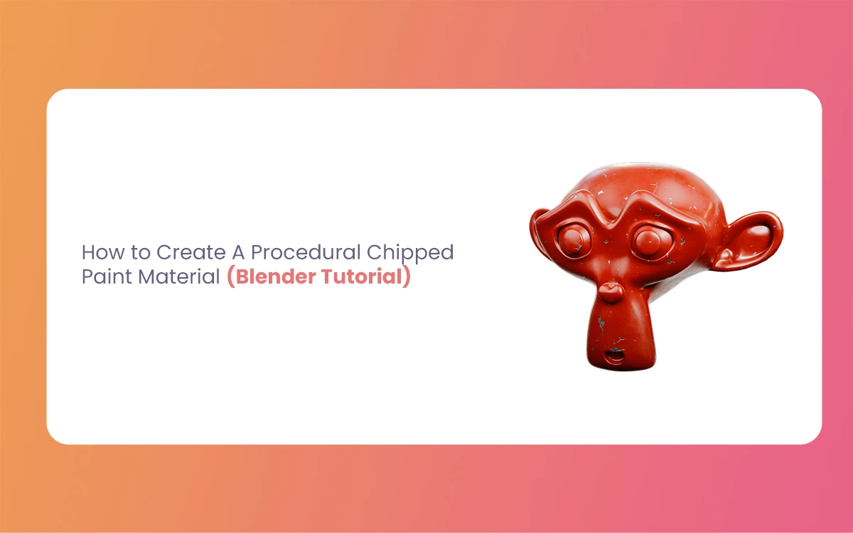
In 3D modeling and rendering, adding realistic surface details can transform a basic model into a compelling piece of art. One of the most commonly sought-after effects is the weathered, worn look of chipped paint revealing underlying materials. This detail authenticates aged machinery, abandoned buildings, or vintage vehicles. The Morphic Studio shares information about creating a fully Procedural Chipped Paint Material in Blender. This allows you to achieve professional-quality results while maintaining complete control over every aspect of the effect.
The beauty of Procedural Chipped Paint Material lies in their flexibility and non-destructive nature. Unlike texture-based approaches that rely on fixed images, procedural materials generate their patterns mathematically, meaning you can infinitely adjust parameters without losing quality or needing to create new texture files. This tutorial will grip Blender’s powerful node-based shader system to create a versatile chipped paint material that can be applied to any object in your scene.
Follow Procedural Materials
What Makes Materials Procedural?
Procedural Chipped Paint Materials are created using mathematical algorithms and node-based systems rather than traditional image textures. In Blender, these materials are built using the Shader Editor, where various nodes can be connected to create complex surface properties. The basic advantages of procedural materials include:
Infinite Resolution: Procedural textures never pixelate, regardless of how close the camera gets
Parametric Control: Every aspect can be adjusted through sliders and values
Memory Efficiency: No need to store large texture files
Perfect Tiling: Procedural patterns naturally tile without visible seams
Easy Variations: Creating multiple versions requires only parameter adjustments
The Shader Editor Workspace
Before diving into the material creation process, it’s essential to understand Blender’s Shader Editor. This workspace provides a visual interface for creating and connecting nodes that define how light interacts with an object’s surface. The editor displays a flow chart-like structure where information flows from left to right, connecting to the Material Output node at the end.
Essential Setup and Preparation
Workspace Configuration
To begin creating your chipped paint material, properly configure your Blender workspace. Start by selecting the object to which you want to apply the material, then switch to the Shading workspace or manually open the Shader Editor. This provides both the 3D viewport and the node editor, allowing you to see real-time updates as you build your material.
Enabling Node Wrangler
One of the most valuable add-ons for shader work is Node Wrangler. This built-in add-on significantly speeds up workflow by providing shortcuts for common operations. To enable it:
Negotiate to Edit > Preferences
Select the Add-ons tab
Search for “Node Wrangler”
Check the box to enable it
With Node Wrangler active, you can use shortcuts like Ctrl+T to automatically add Texture Coordinate and Mapping nodes, saving considerable time during material creation.
Creating the Foundation
Initial Material Setup
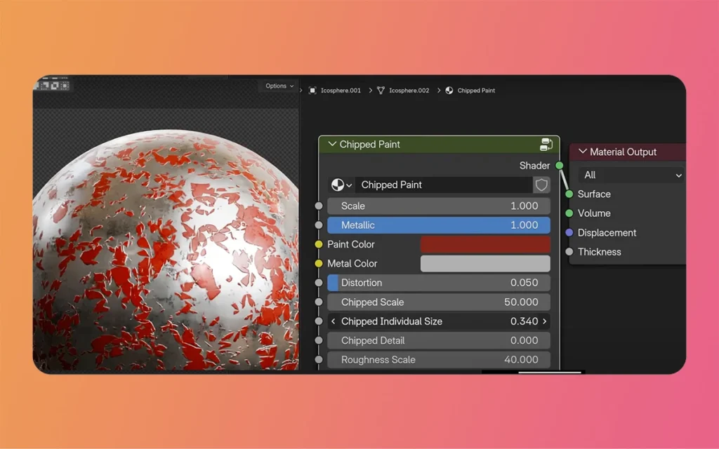
Begin by adding a new material to your selected object. In the Shader Editor, you’ll see a default Principled BSDF shader connected to the Material Output. This will serve as the foundation for your chipped paint material. Name your material “Chipped Paint” for easy identification.
Building the Chip Pattern
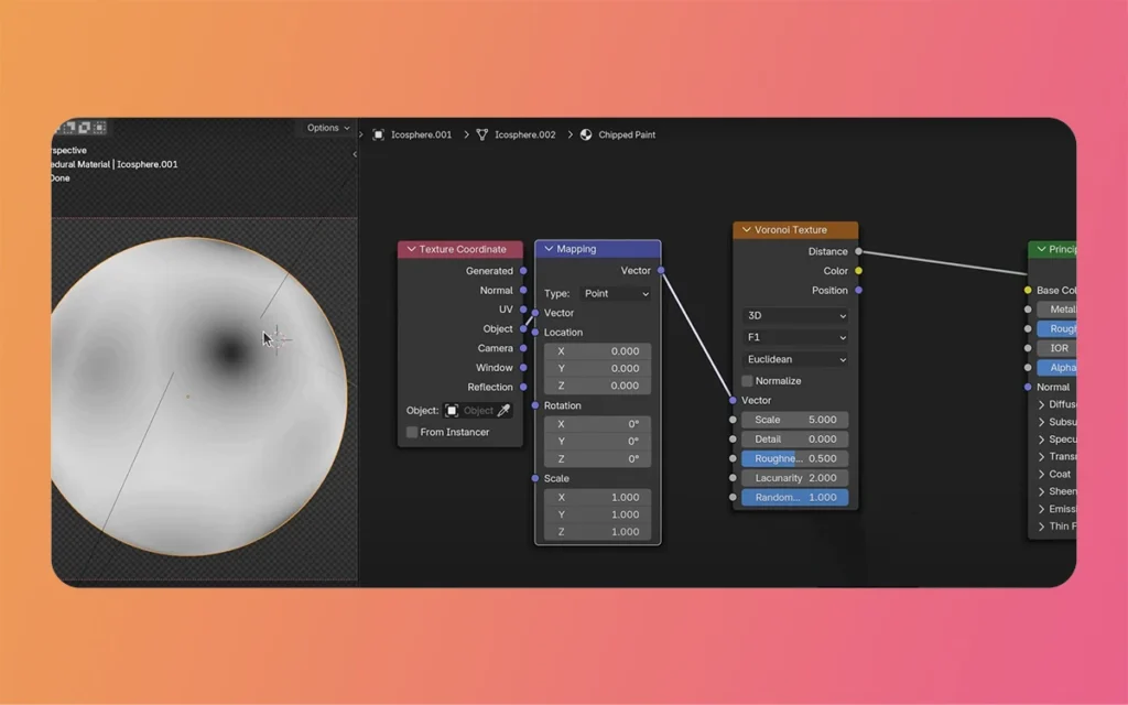
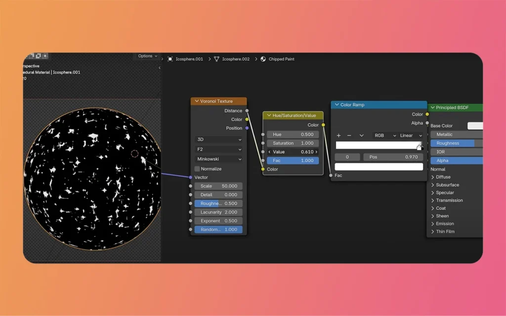
The core of our chipped paint effect relies on the Voronoi Texture node, which generates cellular patterns perfect for simulating paint chips. Add a Voronoi Texture node to your shader network and connect it through a ColorRamp node. This combination allows you to control precisely where chips appear on your surface.
Configure the Voronoi Texture with these settings:
Distance Metric: F2
Feature: Manhattan
Coordinates: Object (for consistent mapping across different objects)
The F2 distance metric creates more organic, irregular patterns, while the Manhattan feature produces sharper, more angular edges—ideal for realistic paint chips.
Developing Realistic Chip Patterns
Fine-tuning the Voronoi Texture
The Scale parameter of the Voronoi Texture controls the general size of your chip pattern. Start with a value around 5-10 and adjust based on your object’s scale and desired chip density. Think of that paint chips vary in size, so don’t make the pattern too uniform.
ColorRamp Control
The ColorRamp node is crucial for defining the areas where paint has chipped away. By adjusting the black and white sliders, you control the proportion of chipped versus intact paint:
Moving sliders closer together creates sharper transitions
Spreading them apart produces more gradual chip edges
The position determines the general amount of chipping
Procedural Chipped Paint Material By The Morphic Studio
Adding Natural Variation
Real paint chips rarely have perfectly uniform edges. To add realistic irregularity, introduce a Noise Texture node into your network. This texture will distort the Voronoi pattern, creating more organic-looking chips:
Add a Noise Texture node
Use a MixRGB node (set to Linear Light mode)
Blend the Noise Texture with your coordinate mapping
Feed this mixed result into the Voronoi Texture’s vector input
The MixRGB factor controls distortion strength—typically, values between 0.1 and 0.3 provide subtle, realistic results.
Creating Multiple Surface Layers
Paint Layer Configuration
For the paint layer, create a Principled BSDF shader with appropriate settings:
Base Color: Choose your desired paint color
Roughness: 0.4-0.6 for typical paint surfaces
Metallic: 0 (paint is non-metallic)
Consider adding slight color variations using a Noise Texture connected to the Base Color through a MixRGB node. This simulates the natural color inconsistencies found in real paint.
Underlying Material Setup
The material revealed by chipped paint is often metal, though it could be wood, concrete, or another surface. For metal:
Add a second Principled BSDF shader
Metallic: 1.0
Base Color: Choose appropriate metal color (darker for iron, brighter for aluminum)
Roughness: 0.2-0.4 for worn metal
Procedural Chipped Paint Material By The Morphic Studio
Combining Layers
Use a Mix Shader node to blend between your paint and underlying material. Connect the ColorRamp output (from your chip pattern) to the Mix Shader’s Factor input. This creates a mask that determines which shader appears where:
Black areas show the paint layer
White areas reveal the underlying material
Adding Surface Detail
Implementing Bump Mapping
To enhance realism, add physical depth to the transition between paint and exposed material:
Add a Bump node to your network
Connect the ColorRamp output to the Bump node’s Height input
Link the Bump node’s Normal output to both Principled BSDF shaders
Adjust the Strength parameter (typically 0.1-0.3)
The bump effect creates the illusion of raised paint edges and recessed chip areas without actual geometry displacement.
Roughness Variation
Paint surfaces rarely have uniform roughness. Add another layer of realism by varying the roughness across the paint surface:
Create a new Noise Texture node
Connect it through a ColorRamp for value control
Feed this into the paint shader’s Roughness input
Fine-tune the noise scale and ColorRamp values
This technique simulates dirt accumulation, wear patterns, and surface irregularities common in aged paint.
Advanced Parameter Control
Creating Custom Node Groups
Once your material is complete, organize it into a custom node group for easy reuse and adjustment:
Select all nodes except the Material Output
Press Ctrl+G to create a group
Inside the group, identify basic parameters to expose
Connect these parameters to the group inputs
This approach creates a clean, professional material with intuitive controls accessible from the main shader view.
Exposed Parameters
Consider exposing these essential controls:
General Scale: Controls the entire material size
Chip Scale: Adjusts individual chip sizes
Chip Amount: Determines the percentage of chipped areas
Distortion: Controls edge irregularity
Paint Color: Easy color changes
Metal Color: Underlying material color
Roughness Values: Surface finish adjustments
Bump Strength: Physical depth of chips
Optimization and Performance
Balancing Quality and Performance
While procedural materials offer incredible flexibility, they can impact render times. Consider these optimization strategies:
Limit noise texture iterations for background objects
Reduce subdivision magnitudes when bump mapping provides sufficient detail
Use simpler shader networks for distant objects
Consider baking procedural textures for animation projects
Render Settings
For best results with procedural materials:
Use Cycles renderer for accurate material representation
Enable appropriate sampling magnitudes (typically 128-256 for final renders)
Consider using adaptive sampling to optimize render times
Enable denoising for cleaner results with fewer samples
Procedural Chipped Paint Material By The Morphic Studio
Actual Applications
Architectural Visualization
Chipped paint materials excel in architectural contexts, particularly for:
Increase noise texture influence and MixRGB factor
Pattern doesn’t scale properly
Incorrect coordinate mapping
Switch to Object coordinates or adjust Mapping node scale
Edges look too sharp
ColorRamp settings too extreme
Adjust ColorRamp positions for softer transitions
Bump effect too strong
Excessive bump strength
Reduce Bump node strength value to 0.1-0.2
Material looks flat
Missing roughness variation
Add noise-driven roughness variations to paint layer
Render times too slow
Complex node network
Simplify noise iterations or bake textures
Seams visible on UV-mapped objects
UV coordinate usage
Switch to Object or Generated coordinates
Colors appear washed out
Incorrect color space
Ensure color textures use sRGB, data textures use Non-Color
Extending the Technique
Multiple Paint Layers
Actual objects often have multiple paint layers. Extend the basic technique by:
Creating additional Voronoi patterns at different scales
Using multiple Mix Shader nodes to blend three or more materials
Varying chip patterns between layers for complex weathering
Adding rust or corrosion effects between layers
Environmental Effects
Enhance realism by incorporating environmental factors:
Add dust accumulation in crevices using Ambient Occlusion
Include moisture effects with glossy variations
Simulate sun-bleaching with gradient-based color variations
Create location-specific wear patterns
Animation Considerations
For animated projects:
Expose time-based parameters for evolving wear patterns
Create drivers linking chip amount to object age
Use object data for location-specific weathering
Implement particle systems for energetic paint flaking
Best Practices
Workflow Efficiency
Maximize your productivity by:
Saving node groups to your asset library
Creating material presets for common scenarios
Using consistent naming conventions
Documenting parameter ranges for each control
Quality Assurance
Ensure professional results through:
Testing materials under various lighting conditions
Checking appearance at different camera distances
Validating performance across different hardware
Maintaining physically plausible parameter values
Future Developments
Blender Evolution
As Blender continues to develop progress, expect:
Enhanced procedural texture options
Improved performance for complex shaders
Better integration with external tools
Advanced weathering presets and templates
Industry Trends
The 3D industry is moving toward:
AI-assisted material creation
Real-time procedural systems
Cloud-based rendering solutions
Standardized material formats
Finally
Creating Procedural Chipped Paint Material in Blender perfectly balances artistic control and technical efficiency. By mastering the techniques defined in this guide, you can produce highly realistic, infinitely customizable weathered surfaces that enhance any 3D project. The procedural approach saves time and storage space and provides the flexibility to adapt materials to any scenario or requirement.
Achieving photorealistic results requires practice and experimentation. Start with the basic setup described here, then gradually incorporate advanced techniques as your Follower’s skill level deepens. Pay attention to actual references, as observing actual chipped paint patterns will inform your artistic decisions and lead to more convincing results.
Whether you’re working on architectural visualization, product design, or entertainment projects, these Procedural Chipped Paint Materials will become an integral part of your Blender toolkit. The initial time investment in learning these techniques pays dividends through increased efficiency, superior quality, and the satisfaction of creating truly professional materials from scratch.
As you continue developing your skills, don’t hesitate to experiment with variations and combinations of the techniques presented here. The beauty of procedural materials lies in their endless possibilities—each project presents new opportunities to refine and expand upon these foundational concepts. With dedication and creativity, you’ll soon be producing chipped paint effects that rival any professional production, all while maintaining the complete control and flexibility that only Procedural Chipped Paint Material can provide.
Best Way To Create Cinematic lighting in Unreal Engine 5 by Morphic Studio [Tutorial]
The Magic of Cinematic lighting in Unreal Engine 5 Have you ever looked at a beautifully rendered game or a virtual film set and wondered how they make it look so incredibly real? Well, the answer almost always comes down to the lighting. Today, we are going to take a look at the magic of […]
July 20, 2026
How To Add Lighting Realistic Rainy Weather in Unreal Engine 5 [Tutorial]
Lighting a stormy environment in Unreal Engine 5 is one of the most rewarding challenges for any 3D environment or lighting artist. Many beginners think that adding rain is as simple as spawning a splash particle system and turning down the sun, but the real secret lies in how light interacts with moisture, clouds, and […]
July 18, 2026
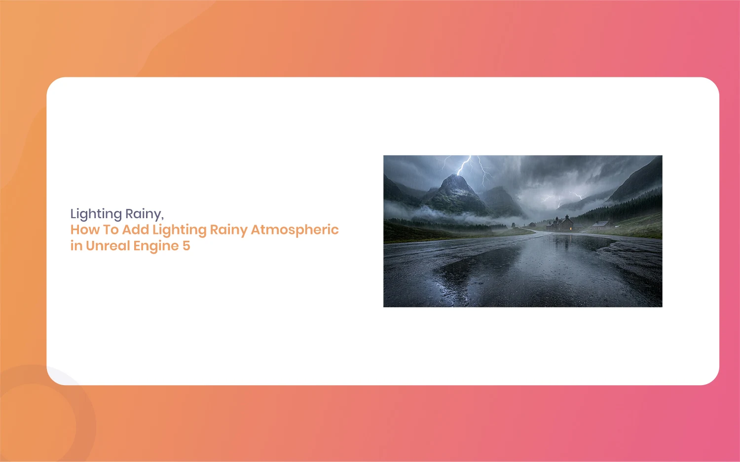
How To Add Lighting Rainy Atmospheric in Unreal Engine 5 [Tutorial]
Hello everyone, and welcome to this new guide. If you are a game developer or a 3D artist, you probably know how important weather is. Creating a moody scene can completely change how a player feels. Today, we are going to look at something very specific. We are going to learn how to add Lighting […]